A study of factors affecting data center airflow in a closed aisle.
Written by Rajesh Nair, Founder & CTO of AdaptivCool, an EEC partner
What happens to the data center airflow through a high-density server when the cold aisle it is in is capped or contained?
Of course, no one would let us do this experiment in their critical data center. So we had to resort to simulating the effect on a computer using a CFD tool.
Every server in a rack is designed to pull enough air through it to cool the electronics in it under all specified environmental conditions. The front and rear doors of a rack and cabling in it can add additional series flow impedance to the internal impedance of the server. The server fans can overcome additional impedance to some extent since they are normally over-designed. Having enough cold air available in an open cold aisle helps overcome some of these airflow restrictions. However, when the cold aisle is capped (contained) the situation changes a lot.
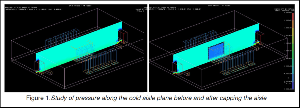
In the simulation study below, we modeled an existing data center. The pressure pattern along the whole data center cold aisle is shown in Figure 1 as shaded plane. The pressure stays relatively flat along the whole length of the room. We modified the model by capping the cold aisle and studied the pressure in the same plane. Nothing else in the room was changed. As the figure shows, the pressure in the cold aisle dropped significantly. A lower server intake pressure increases the pressure difference the server fan has to work against, causing the airflow to drop. Here is an electrical engineer’s analysis of aisle capping on server pressure and airflow.
Airflow through a server enclosure:
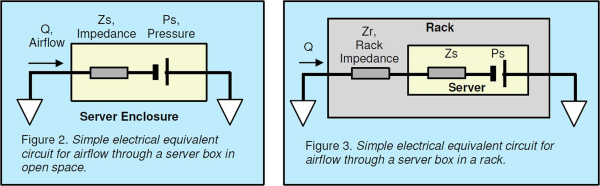
Server boxes are designed to operate under wide thermal environmental conditions. The built-in fan is capable of pulling enough air to cool the electronics in the box. In Figure 2, a simple electrical representation of airflow is shown. The air intake and exhaust are the open room space and are at the same pressure. The fan creates enough pressure (Ps) to create airflow (Q) over the internal impedance (Zs). The fan speed determines the driving pressure and airflow. The internal control system modulates the fan speed to draw just enough air to cool the electronics. Once this server is placed in a rack it sees additional impedance, Zr, from the front and rear doors and cabling in the path of airflow (Figure 3). The server fan now needs to operate at a higher speed to compensate for these series impedances to get enough airflow to cool the devices inside. This may be acceptable to a limit since these systems are normally over-designed. But at the extreme thermal conditions this additional impedance, Zr, may limit the cooling capacity of these servers. So it is important to minimize Zr.
Airflow in a closed aisle:
Once the cold aisle is closed, the airflow-pressure scenario changes further. Since the aisle is closed, the aisle pressure (Pa) may not be at the same as the pressure in the hot aisle. As shown in Figure 4, there are two series airmovers in the airflow path; the CRAC and the server fan. The pressure created by the CRAC (Pc) causes airflow under the floor to overcome the under floor impedance (Zu) and the impedance of tiles in the cold aisle (Zt). Depending on the distance from the CRAC to the aisle and underfloor impedance, the airflow could vary significantly from one closed aisle to another. In Figure 1 the CRAC fans were not creating enough pressure to discharge air into the closed aisle. In fact, the fans in the servers were pulling cold air into the aisle thus causing a lower pressure in the aisle than the rest of the room. The net airflow through the servers dropped significantly once the aisle is closed. One fix to increase airflow through the servers is to increase the aisle pressure by using more open grates (and thus reduce Zt). This could still only be a temporary solution. The pressure in an aisle is influenced by multiple CRACs. If the CRAC with highest influence is turned off, the aisle pressure can immediately drop and other CRACs may not be able to compensate.

Pressure compensation in a closed aisle:
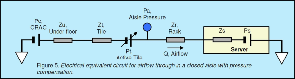
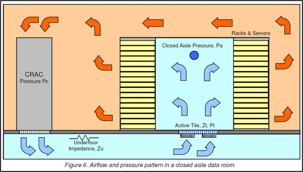
The way to guarantee airflow through servers in a contained aisle is by controlling the pressure in the aisle. An effective way is by use of either a fan assisted active tile (Demand Based Cooling system from AdaptivCool), or fan assisted chimney or rack backdoor with automatic speed control. The last two options need to be installed on each rack, as these manage pressure drop only within a rack. The active tiles (Figure 5) can control pressure in the whole aisle and compensate for CRAC failure. The cold to hot aisle pressure difference is used for fan speed control. This approach can offer normal server operation in a closed aisle even under CRAC failure conditions. Figure 6 is a representation of airflow and pressure in the room.
Closing:
The primary advantage of data center aisle containment is improved cooling efficiency, by avoiding mixing of cold and hot air in a data center. It also comes with unintended consequences. The two important ones are decreased data center airflow and loss of redundancy to CRAC failures. Both of these can be addressed by using additional fan assisted tiles in the airflow path that can hold a steady aisle pressure as well as compensate for CRAC failures.
To learn more about data center airflow best practices, fill out our contact us form or contact Brad Morgan, our Data Center Cooling Solutions Manager at bmorgan@eecnet.com or 508-229-1446.